Optic Sweep Art Optic Center Eye Scan Design Science
| Optical coherence tomography | |
|---|---|
 Optical coherence tomography (OCT) epitome of a sarcoma | |
| MeSH | D041623 |
| OPS-301 lawmaking | iii-300 |
Optical coherence tomography (OCT) is an imaging technique that uses low-coherence light to capture micrometer-resolution, two- and three-dimensional images from within optical handful media (e.g., biological tissue). It is used for medical imaging and industrial nondestructive testing (NDT). Optical coherence tomography is based on low-coherence interferometry, typically employing near-infrared lite. The apply of relatively long wavelength lite allows information technology to penetrate into the scattering medium. Confocal microscopy, another optical technique, typically penetrates less deeply into the sample but with higher resolution.
Depending on the properties of the calorie-free source (superluminescent diodes, ultrashort pulsed lasers, and supercontinuum lasers take been employed), optical coherence tomography has accomplished sub-micrometer resolution (with very broad-spectrum sources emitting over a ~100 nm wavelength range).[ commendation needed ] [ verification needed ]
Optical coherence tomography is one of a grade of optical tomographic techniques.[ commendation needed ] Commercially available optical coherence tomography systems are employed in diverse applications, including art conservation and diagnostic medicine, notably in ophthalmology and optometry where it can be used to obtain detailed images from within the retina.[ citation needed ] Recently, it has also begun to be used in interventional cardiology to help diagnose coronary artery disease,[1] and in dermatology to improve diagnosis.[2] A relatively recent implementation of optical coherence tomography, frequency-domain optical coherence tomography, provides advantages in the bespeak-to-dissonance ratio provided, thus permitting faster point acquisition.[ citation needed ] OCT is not the same as Optical coherence microscopy (OCM), which "is a microscopic incarnation of optical coherence tomography (October)"[iii] that can be used for 3D imaging reconstruction through intrinsic contrasting of back-scattered (coherent) light.[4]
Introduction [edit]
Optical coherence tomogram of a fingertip. It is possible to observe the sweat glands, having "corkscrew advent"
Starting from Adolf Fercher and colleagues' work on depression-, partial coherence or white-low-cal interferometry for in vivo ocular center measurements[5] [6] in Vienna in the 1980s, imaging of biological tissue, especially of the homo middle, was investigated in parallel by multiple groups worldwide. A first two-dimensional in vivo delineation of a human eye fundus along a horizontal meridian based on white light interferometric depth scans was presented at the ICO-15 Saturday conference in 1990.[seven] Further developed in 1990 by Naohiro Tanno,[viii] [9] then a professor at Yamagata University it was referred to as heterodyne reflectance tomography, and in particular since 1991 by Huang et al., in Prof. James Fujimoto laboratory at Massachusetts Establish of Technology,[10] who successfully coined the term "optical coherence tomography". Since then, October with micrometer resolution and cross-exclusive imaging capabilities has become a prominent biomedical tissue-imaging technique that continuously picked up new technical capabilities starting from early on electronic signal detection, via utilisation of broadband lasers and linear pixel arrays to ultrafast tuneable lasers to expand its performance and sensitivity envelope.
It is particularly suited to ophthalmic applications and other tissue imaging requiring micrometer resolution and millimeter penetration depth.[xi] Showtime in vivo OCT images – displaying retinal structures – were published in 1993 and first endoscopic images in 1997.[12] [13] OCT has also been used for various art conservation projects, where it is used to analyze unlike layers in a painting. October has interesting advantages over other medical imaging systems. Medical ultrasonography, magnetic resonance imaging (MRI), confocal microscopy, and OCT are differently suited to morphological tissue imaging: while the first ii accept whole body but low resolution imaging capability (typically a fraction of a millimeter), the 3rd 1 tin provide images with resolutions well beneath 1 micrometer (i.e. sub-cellular), between 0 and 100 micrometers in depth, and the fourth can probe as deep as 500 micrometers, but with a lower (i.e. architectural) resolution (around 10 micrometers in lateral and a few micrometers in depth in ophthalmology, for case, and 20 micrometers in lateral in endoscopy).[xiv] [15]
Oct is based on low-coherence interferometry.[sixteen] [17] [ page needed ] [6] In conventional interferometry with long coherence length (i.e., laser interferometry), interference of low-cal occurs over a distance of meters. In OCT, this interference is shortened to a distance of micrometers, owing to the use of broad-bandwidth light sources (i.eastward., sources that emit light over a broad range of frequencies). Calorie-free with broad bandwidths can be generated by using superluminescent diodes or lasers with extremely brusk pulses (femtosecond lasers). White light is an example of a broadband source with lower ability.
Light in an OCT organisation is broken into ii arms – a sample arm (containing the particular of interest) and a reference arm (usually a mirror). The combination of reflected light from the sample arm and reference lite from the reference arm gives rise to an interference pattern, only only if lite from both arms take traveled the "same" optical altitude ("same" significant a difference of less than a coherence length). Past scanning the mirror in the reference arm, a reflectivity profile of the sample can be obtained (this is time domain OCT). Areas of the sample that reverberate back a lot of light volition create greater interference than areas that don't. Any light that is exterior the short coherence length volition not interfere.[18] This reflectivity profile, called an A-scan, contains data well-nigh the spatial dimensions and location of structures within the item of interest. A cross-sectional tomogram (B-browse) may be achieved by laterally combining a series of these axial depth scans (A-scan). A face imaging at an acquired depth is possible depending on the imaging engine used.
Layperson's caption [edit]

Ocular October retinal thickness map, right center

Time-domain OCT of the macular area of a retina at 800 nm, axial resolution 3 µm
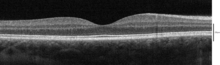
Spectral-domain OCT macula cross-section scan.
Optical coherence tomography (OCT) is a technique for obtaining sub-surface images of translucent or opaque materials at a resolution equivalent to a low-power microscope. Information technology is effectively 'optical ultrasound', imaging reflections from within tissue to provide cross-exclusive images.[19]
October has attracted interest among the medical community because it provides tissue morphology imagery at much higher resolution (less than 10 μm axially and less than xx μm laterally[20] ) than other imaging modalities such as MRI or ultrasound.
The primal benefits of October are:
- Live sub-surface images at near-microscopic resolution
- Instant, straight imaging of tissue morphology
- No training of the sample or subject area, no contact
- No ionizing radiation
October delivers high resolution because it is based on light, rather than sound or radio frequency. An optical beam is directed at the tissue, and a small portion of this light that reflects from sub-surface features is collected. Notation that almost low-cal is not reflected but, rather, scatters off at large angles. In conventional imaging, this diffusely scattered light contributes background that obscures an image. Even so, in October, a technique chosen interferometry is used to record the optical path length of received photons allowing rejection of most photons that besprinkle multiple times before detection. Thus Oct tin can build up clear 3D images of thick samples by rejecting groundwork signal while collecting low-cal straight reflected from surfaces of interest.
Within the range of noninvasive 3-dimensional imaging techniques that have been introduced to the medical research community, Oct as an echo technique is like to ultrasound imaging. Other medical imaging techniques such as computerized axial tomography, magnetic resonance imaging, or positron emission tomography practise non utilise the echo-location principle.[21]
The technique is limited to imaging 1 to two mm below the surface in biological tissue, because at greater depths the proportion of low-cal that escapes without scattering is too small to be detected. No special preparation of a biological specimen is required, and images tin can exist obtained 'non-contact' or through a transparent window or membrane. It is also of import to note that the laser output from the instruments used is depression – center-prophylactic about-infrared or visible-light [22] – and no damage to the sample is therefore probable.
Theory [edit]
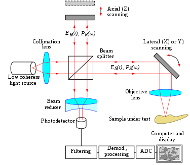
The principle of Oct is white low-cal, or low coherence, interferometry. The optical setup typically consists of an interferometer (Fig. 1, typically Michelson type) with a low coherence, broad bandwidth light source. Lite is divide into and recombined from reference and sample arm, respectively.
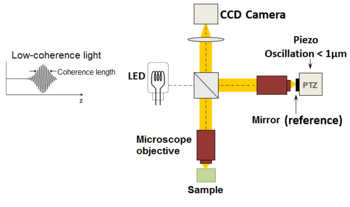
| Fig. 2 Typical optical setup of single point OCT. Scanning the light beam on the sample enables not-invasive cross-exclusive imaging up to 3 mm in depth with micrometer resolution. | Fig. 1 Full-field OCT optical setup. Components include: super-luminescent diode (SLD), convex lens (L1), 50/50 beamsplitter (BS), camera objective (CO), CMOS-DSP camera (CAM), reference (REF), and sample (SMP). The photographic camera functions every bit a 2-dimensional detector array, and with the Oct technique facilitating scanning in depth, a not-invasive three dimensional imaging device is achieved. |
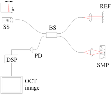
| Fig. four Spectral discrimination by fourier-domain OCT. Components include: depression coherence source (LCS), beamsplitter (BS), reference mirror (REF), sample (SMP), diffraction grating (DG) and full-field detector (CAM) acting every bit a spectrometer, and digital signal processing (DSP) | Fig. 3 Spectral discrimination by swept-source October. Components include: swept source or tunable laser (SS), beamsplitter (BS), reference mirror (REF), sample (SMP), photodetector (PD), and digital signal processing (DSP) |


Time domain [edit]

In time domain Oct the pathlength of the reference arm is varied in time (the reference mirror is translated longitudinally). A property of depression coherence interferometry is that interference, i.e. the serial of dark and bright fringes, is just accomplished when the path difference lies inside the coherence length of the light source. This interference is called auto correlation in a symmetric interferometer (both arms accept the aforementioned reflectivity), or cantankerous-correlation in the common case. The envelope of this modulation changes as pathlength departure is varied, where the peak of the envelope corresponds to pathlength matching.
The interference of two partially coherent calorie-free beams tin can be expressed in terms of the source intensity, , as

![I = k_1 I_S + k_2 I_S + 2 \sqrt { \left ( k_1 I_S \right ) \cdot \left ( k_2 I_S \right )} \cdot Re \left [\gamma \left ( \tau \right ) \right] \qquad (1)](https://wikimedia.org/api/rest_v1/media/math/render/svg/e90b482fe73988b986f3ebc89f0ff288bf6d67d9)
where represents the interferometer beam splitting ratio, and is called the circuitous degree of coherence, i.east. the interference envelope and carrier dependent on reference arm browse or time delay , and whose recovery is of involvement in October. Due to the coherence gating effect of OCT the complex degree of coherence is represented as a Gaussian function expressed equally[half-dozen]


![\gamma \left ( \tau \right ) = \exp \left [- \left ( \frac{\pi\Delta\nu\tau}{2 \sqrt{\ln 2} } \right )^2 \right] \cdot \exp \left ( -j2\pi\nu_0\tau \right ) \qquad \quad (2)](https://wikimedia.org/api/rest_v1/media/math/render/svg/83da0d10e1049d9b461ab144e7b9dd7e58e85c45)
where represents the spectral width of the source in the optical frequency domain, and is the centre optical frequency of the source. In equation (2), the Gaussian envelope is amplitude modulated past an optical carrier. The summit of this envelope represents the location of the microstructure of the sample under test, with an amplitude dependent on the reflectivity of the surface. The optical carrier is due to the Doppler result resulting from scanning 1 arm of the interferometer, and the frequency of this modulation is controlled by the speed of scanning. Therefore, translating one arm of the interferometer has two functions; depth scanning and a Doppler-shifted optical carrier are accomplished by pathlength variation. In October, the Doppler-shifted optical carrier has a frequency expressed as


where is the central optical frequency of the source, is the scanning velocity of the pathlength variation, and is the speed of light.


interference signals in TD vs. FD-OCT
The centric and lateral resolutions of OCT are decoupled from one another; the former being an equivalent to the coherence length of the light source and the latter being a part of the optics. The axial resolution of OCT is defined as
where and are respectively the primal wavelength and the spectral width of the light source.[23]


Frequency domain [edit]
In frequency domain Oct (FD-OCT) the broadband interference is acquired with spectrally separated detectors. Two common approaches are swept-source and spectral-domain OCT. A swept source Oct encodes the optical frequency in time with a spectrally scanning source. A spectral domain Oct uses a dispersive detector, like a grating and a linear detector array, to separate the different wavelengths. Due to the Fourier relation (Wiener–Khinchin theorem between the auto correlation and the spectral ability density) the depth scan tin can be immediately calculated by a Fourier-transform from the acquired spectra, without motility of the reference arm.[24] [25] This feature improves imaging speed dramatically, while the reduced losses during a single scan improve the indicate to noise ratio proportional to the number of detection elements. The parallel detection at multiple wavelength ranges limits the scanning range, while the full spectral bandwidth sets the centric resolution.[26]
Spatially encoded [edit]
Spatially encoded frequency domain OCT (SEFD-Oct, spectral domain or Fourier domain OCT) extracts spectral information by distributing dissimilar optical frequencies onto a detector stripe (line-array CCD or CMOS) via a dispersive element (run into Fig. 4). Thereby the information of the total depth scan tin can be caused within a unmarried exposure. Notwithstanding, the large signal to noise advantage of FD-OCT is reduced due to the lower dynamic range of stripe detectors with respect to single photosensitive diodes, resulting in an SNR (point to noise ratio) reward of ~ten dB at much college speeds. This is not much of a problem when working at 1300 nm, however, since dynamic range is not a serious problem at this wavelength range.[23]
The drawbacks of this technology are found in a potent fall-off of the SNR, which is proportional to the distance from the zero delay and a sinc-type reduction of the depth dependent sensitivity because of limited detection linewidth. (One pixel detects a quasi-rectangular portion of an optical frequency range instead of a single frequency, the Fourier-transform leads to the sinc(z) beliefs). Additionally the dispersive elements in the spectroscopic detector ordinarily do non distribute the low-cal every bit spaced in frequency on the detector, only mostly accept an inverse dependence. Therefore, the signal has to exist resampled before processing, which can not take intendance of the difference in local (pixelwise) bandwidth, which results in further reduction of the indicate quality. Yet, the fall-off is not a serious problem with the development of new generation CCD or photodiode array with a larger number of pixels.
Synthetic array heterodyne detection offers some other approach to this trouble without the need for high dispersion.
Time encoded [edit]
Time encoded frequency domain Oct (TEFD-OCT, or swept source OCT) tries to combine some of the advantages of standard TD and SEFD-OCT. Here the spectral components are not encoded by spatial separation, merely they are encoded in time. The spectrum is either filtered or generated in unmarried successive frequency steps and reconstructed before Fourier-transformation. By accommodation of a frequency scanning light source (i.e. frequency scanning laser) the optical setup (come across Fig. 3) becomes simpler than SEFD, but the trouble of scanning is essentially translated from the TD-October reference-arm into the TEFD-Oct light source. Here the advantage lies in the proven loftier SNR detection engineering, while swept laser sources achieve very small instantaneous bandwidths (linewidths) at very high frequencies (20–200 kHz). Drawbacks are the nonlinearities in the wavelength (peculiarly at loftier scanning frequencies), the broadening of the linewidth at high frequencies and a high sensitivity to movements of the scanning geometry or the sample (below the range of nanometers within successive frequency steps).
Full-field Oct [edit]
Schematic view of a full-field October
An imaging approach to temporal OCT was developed past Claude Boccara'southward team in 1998,[27] with an conquering of the images without beam scanning. In this technique called total-field October (FF-OCT), unlike other OCT techniques that acquire cross-sections of the sample, the images are here "en-face" i.e. like images of classical microscopy: orthogonal to the light beam of illumination.[28]
More precisely, interferometric images are created by a Michelson interferometer where the path length departure is varied past a fast electric component (normally a piezo mirror in the reference arm). These images acquired past a CCD photographic camera are combined in mail-treatment (or on-line) past the phase shift interferometry method, where usually 2 or iv images per modulation period are acquired, depending on the algorithm used.[29] [xxx] More recently, approaches that allow rapid single-shot imaging were developed to simultaneously capture multiple phase-shifted images required for reconstruction, using single photographic camera.[31] Single-shot time-domain OCM is limited only by the camera frame rate and available illumination.
The "en-confront" tomographic images are thus produced by a wide-field illumination, ensured past the Linnik configuration of the Michelson interferometer where a microscope objective is used in both arms. Furthermore, while the temporal coherence of the source must remain depression equally in classical OCT (i.e. a broad spectrum), the spatial coherence must likewise be depression to avoid parasitical interferences (i.e. a source with a large size).[32]
Line-field (confocal) OCT [edit]
Line-field confocal optical coherence tomography (LC-OCT) is an imaging technique based on the principle of time-domain Oct with line illumination using a broadband light amplification by stimulated emission of radiation and line detection using a line-scan photographic camera.[33] LC-OCT produces B-scans in real-time from multiple A-scans caused in parallel. En face likewise as iii-dimensional images can also be obtained past scanning the illumination line laterally.[34] [35] The focus is continuously adapted during the scan of the sample depth, using a high numerical aperture (NA) microscope objective to image with high lateral resolution. Past using a supercontinuum laser as a light source, a quasi-isotropic spatial resolution of ~ 1 µm is achieved at a central wavelength of ~ 800 nm. On the other hand, line illumination and detection, combined with the use of a loftier NA microscope objective, produce a confocal gate that prevents near scattered light that does not contribute to the signal from beingness detected by the photographic camera. This confocal gate, which is absent in the full-field OCT technique, gives LC-OCT an reward in terms of detection sensitivity and penetration in highly handful media such as skin tissues.[36] So far this technique has been used mainly for peel imaging in the fields of dermatology[37] [38] [39] [40] [41] [42] and cosmetology.[43]
Scanning schemes [edit]
Focusing the lite beam to a point on the surface of the sample under test, and recombining the reflected low-cal with the reference will yield an interferogram with sample data corresponding to a single A-browse (Z axis but). Scanning of the sample can exist achieved by either scanning the calorie-free on the sample, or by moving the sample under test. A linear scan will yield a two-dimensional data fix respective to a cross-exclusive image (X-Z axes browse), whereas an surface area browse achieves a three-dimensional data set corresponding to a volumetric image (X-Y-Z axes scan).
Single point [edit]
Systems based on single point, confocal, or flying-spot time domain OCT, must scan the sample in two lateral dimensions and reconstruct a three-dimensional image using depth information obtained past coherence-gating through an axially scanning reference arm (Fig. 2). 2-dimensional lateral scanning has been electromechanically implemented past moving the sample[25] using a translation phase, and using a novel micro-electro-mechanical system scanner.[44]
Parallel [edit]
Parallel or full field October using a charge-coupled device (CCD) photographic camera has been used in which the sample is full-field illuminated and en face imaged with the CCD, hence eliminating the electromechanical lateral browse. By stepping the reference mirror and recording successive en face images a 3-dimensional representation tin be reconstructed. Iii-dimensional October using a CCD camera was demonstrated in a phase-stepped technique,[45] using geometric phase shifting with a Linnik interferometer,[46] utilising a pair of CCDs and heterodyne detection,[47] and in a Linnik interferometer with an aquiver reference mirror and axial translation phase.[48] Primal to the CCD approach is the necessity for either very fast CCDs or carrier generation dissever to the stepping reference mirror to rails the high frequency Oct carrier.
Smart detector array [edit]
A two-dimensional smart detector array, made using a ii µm complementary metal-oxide-semiconductor (CMOS) process, was used to demonstrate full-field TD-October.[49] Featuring an elementary optical setup (Fig. 3), each pixel of the 58x58 pixel smart detector array acted as an individual photodiode and included its ain hardware demodulation circuitry.
Selected applications [edit]
Optical coherence tomography is an established medical imaging technique and is used beyond several medical specialties including ophthalmology and cardiology, and is widely used in basic science enquiry applications.
Ophthalmology [edit]
Ocular (or ophthalmic) Oct is used heavily past ophthalmologists and optometrists to obtain high-resolution images of the retina and inductive segment. Owing to Oct's capability to evidence cross-sections of tissue layers with micrometer resolution, October provides a straightforward method of assessing cellular organization, photoreceptor integrity,[50] [51] [52] [53] and axonal thickness in glaucoma,[54] macular degeneration,[55] diabetic macular edema,[56] multiple sclerosis[57] and other eye diseases or systemic pathologies which accept ocular signs.[58] Additionally, ophthalmologists leverage Oct to assess the vascular wellness of the retina via a technique called OCT angiography (OCTA).[59] In ophthalmological surgery, peculiarly retinal surgery, an OCT can be mounted on the microscope. Such a system is called an intraoperative OCT (iOCT) and provides back up during the surgery with clinical benefits.[60] [61] [62] Polarization-sensitive Oct was recently applied in the human being retina to determine optical polarization properties of vessel walls virtually the optic nervus.[63]
Cardiology and intravascular applications [edit]
In the setting of cardiology, October is used to epitome coronary arteries in order to visualize vessel wall lumen morphology and microstructure at a resolution 10 times college than other existing modalities such as intravascular ultrasounds, and x-ray angiography (intracoronary optical coherence tomography). For this type of application, approximately 1 mm in diameter cobweb-optics catheters are used to access avenue lumen through semi-invasive interventions such equally percutaneous coronary interventions.
The beginning demonstration of endoscopic Oct was reported in 1997, by researchers in James Fujimoto laboratory at Massachusetts Institute of Technology, including Prof. Guillermo James Tearney and Prof. Brett Bouma.[64] The commencement TD-October imaging catheter and arrangement was commercialized by LightLab Imaging, Inc., a company based in Massachusetts in 2006. The first FD-OCT imaging study was reported by the laboratory of Prof. Guillermo J. Tearney and Prof. Brett Bouma based at Massachusetts Full general Hospital in 2008.[65] Intravascular FD-OCT was kickoff introduced in the market in 2009 by LightLab Imaging, Inc.[66] and Terumo Corporation launched a second solution for coronary artery imaging in 2012. The higher imaging speed of FD-October enabled the widespread adoption of this imaging technology for coronary artery imaging. Information technology is estimated that over 100,000 FD-OCT coronary imaging cases are performed yearly, and that the market is increasing past approximately 20% every year.[67]
Intravascular OCT has been investigated for use in neurovascular applications, also, including imaging for guiding endovascular treatment of ischemic stroke and encephalon aneurysms.[68] Clinical utilise has been limited to proximal intracranial anatomy of patient with limited tortuosity, showing the potential of OCT for the imaging of neurovascular affliction.[69] An intravascular OCT imaging catheter design tailored for apply in tortuous neurovascular beefcake has been proposed in 2020.[70]
Further developments of intravascular OCT included the combination with other optical imaging modalities (multi-modality imaging). Oct has been combined with fluorescence molecular imaging to enhance its adequacy to find molecular/functional and tissue morphological information simultaneously.[71] In a similar way, combination with near-infrared spectroscopy has been also demonstrated.
Oncology [edit]
Endoscopic October has been applied to the detection and diagnosis of cancer and precancerous lesions, such as Barrett's esophagus and esophageal dysplasia.[72]
Dermatology [edit]
The start use of OCT in dermatology dates dorsum to 1997.[73] Since and then, Oct has been applied to the diagnosis of various peel lesions including carcinomas.[74] [75] [76] However, the diagnosis of melanoma using conventional OCT is hard, especially due to insufficient imaging resolution.[77] Emerging high-resolution October techniques such as LC-Oct take the potential to better the clinical diagnostic process, allowing for the early detection of malignant skin tumors – including melanoma – and a reduction in the number of surgical excisions of benign lesions.[78] Other promising areas of application include the imaging of lesions where excisions are hazardous or impossible and the guidance of surgical interventions through identification of tumor margins.
Dentistry [edit]
Researchers in Tokyo medical and Dental University were able to detect enamel white spot lesions around and below the orthodontic brackets using swept source October.[79]
Research applications [edit]
Researchers have used OCT to produce detailed images of mice brains, through a "window" made of zirconia that has been modified to exist transparent and implanted in the skull.[eighty] Optical coherence tomography is too applicable and increasingly used in industrial applications, such as nondestructive testing (NDT), textile thickness measurements,[81] and in detail sparse silicon wafers[82] [83] and compound semiconductor wafers thickness measurements[84] [85] surface roughness characterization, surface and cross-section imaging[86] [87] and volume loss measurements. October systems with feedback can exist used to control manufacturing processes. With high speed data acquisition,[88] and sub-micron resolution, OCT is adjustable to perform both inline and off-line.[89] Due to the high volume of produced pills, an interesting field of application is in the pharmaceutical industry to control the coating of tablets.[90] Fiber-based OCT systems are particularly adaptable to industrial environments.[91] These tin access and scan interiors of hard-to-reach spaces,[92] and are able to operate in hostile environments—whether radioactive, cryogenic, or very hot.[93] Novel optical biomedical diagnostic and imaging technologies are currently being developed to solve problems in biology and medicine.[94] As of 2014, attempts have been made to utilise optical coherence tomography to identify root canals in teeth, specifically canal in the maxillary molar, yet, there is no difference with the electric current methods of dental operatory microscope.[95] [96] [ not-main source needed ] Research conducted in 2015 was successful in utilizing a smartphone as an OCT platform, although much work remains to exist done before such a platform would be commercially feasible.[97] Photonic integrated circuits may be a promising option to miniaturized OCT. Similarly to integrated circuits silicon-based fabrication techniques can be used to produced miniaturized photonic systems. Start in vivo human retinal imaging has been reported recently [98]
See besides [edit]
- Angle-resolved depression-coherence interferometry
- Ballistic photon
- Confocal microscopy
- Interferometry
- Intracoronary optical coherence tomography
- Leica Microsystems
- Medical imaging
- Novacam Technologies
- Optical heterodyne detection
- Optical projection tomography
- Spectroscopic optical coherence tomography
- Terahertz tomography
- Tomography
References [edit]
- ^ Bezerra HG, Costa MA, Guagliumi G, Rollins AM, Simon DI (November 2009). "Intracoronary optical coherence tomography: a comprehensive review clinical and research applications". JACC. Cardiovascular Interventions. 2 (11): 1035–1046. doi:ten.1016/j.jcin.2009.06.019. PMC4113036. PMID 19926041.
- ^ Chua Due south (2015). "Loftier-Definition Optical Coherence Tomography for the Study of Development of a Disease" (PDF). Dermatology Bulletin. 26 (i): ii–3. Retrieved 28 May 2015.
- ^ Karnowski G, Ajduk A, Wieloch B, Tamborski Southward, Krawiec One thousand, Wojtkowski One thousand, Szkulmowski M (June 2017). "Optical coherence microscopy equally a novel, non-invasive method for the 4D live imaging of early on mammalian embryos". Scientific Reports. 7 (1): 4165. Bibcode:2017NatSR...seven.4165K. doi:10.1038/s41598-017-04220-viii. PMC5482811. PMID 28646146.
- ^ Zhu J, Freitas HR, Maezawa I, Jin LW, Srinivasan VJ (July 2021). "1700 nm optical coherence microscopy enables minimally invasive, label-free, in vivo optical biopsy deep in the mouse brain". Calorie-free, Scientific discipline & Applications. 10 (1): 145. Bibcode:2021LSA....10..145Z. doi:ten.1038/s41377-021-00586-7. PMC8280201. PMID 34262015.
- ^ Fercher AF, Roth E (15 September 1986). Mueller GJ (ed.). "Ophthalmic laser interferometry". Proc. SPIE. Optical Instrumentation for Biomedical Laser Applications. 658: 48–51. Bibcode:1986SPIE..658...48F. doi:10.1117/12.938523. S2CID 122883903.
- ^ a b c Fercher AF, Mengedoht K, Werner W (March 1988). "Eye-length measurement past interferometry with partially coherent light". Optics Letters. thirteen (3): 186–8. Bibcode:1988OptL...13..186F. doi:x.1364/OL.13.000186. PMID 19742022.
- ^ Fercher AF (12–16 August 1990). "Ophthalmic interferometry". In von Bally G, Khanna S (eds.). Proceedings of the International Conference on Optics in Life Sciences. Garmisch-Partenkirchen, Germany. pp. 221–228. ISBN0-444-89860-3.
- ^ Naohiro Tanno, Tsutomu Ichikawa, Akio Saeki: "Lightwave Reflection Measurement," Japanese Patent # 2010042 (1990) (Japanese Language)
- ^ Shinji Chiba; Naohiro Tanno (1991). Backscattering Optical Heterodyne Tomography. 14th Laser Sensing Symposium (in Japanese).
- ^ Huang D, Swanson EA, Lin CP, Schuman JS, Stinson WG, Chang Westward, et al. (November 1991). "Optical coherence tomography". Science. 254 (5035): 1178–81. Bibcode:1991Sci...254.1178H. doi:x.1126/science.1957169. PMC4638169. PMID 1957169.
- ^ Zysk AM, Nguyen FT, Oldenburg AL, Marks DL, Boppart SA (2007). "Optical coherence tomography: a review of clinical evolution from demote to bedside". Journal of Biomedical Optics. 12 (5): 051403. Bibcode:2007JBO....12e1403Z. doi:ten.1117/1.2793736. PMID 17994864. S2CID 20621284.
- ^ Fercher AF, Hitzenberger CK, Drexler Due west, Kamp G, Sattmann H (July 1993). "In vivo optical coherence tomography". American Periodical of Ophthalmology. 116 (one): 113–4. doi:ten.1016/S0002-9394(14)71762-3. PMID 8328536.
- ^ Swanson EA, Izatt JA, Hee MR, Huang D, Lin CP, Schuman JS, et al. (November 1993). "In vivo retinal imaging by optical coherence tomography". Eyes Letters. xviii (21): 1864–6. Bibcode:1993OptL...18.1864S. doi:10.1364/OL.xviii.001864. PMID 19829430. S2CID 21218566.
- ^ Drexler W, Morgner U, Ghanta RK, Kärtner FX, Schuman JS, Fujimoto JG (April 2001). "Ultrahigh-resolution ophthalmic optical coherence tomography". Nature Medicine. 7 (4): 502–7. doi:10.1038/86589. PMC1950821. PMID 11283681.
- ^ Kaufman SC, Musch DC, Belin MW, Cohen EJ, Meisler DM, Reinhart WJ, et al. (February 2004). "Confocal microscopy: a study by the American Academy of Ophthalmology". Ophthalmology. 111 (2): 396–406. doi:10.1016/j.ophtha.2003.12.002. PMID 15019397.
- ^ Riederer SJ (2000). "Current technical development of magnetic resonance imaging". IEEE Engineering in Medicine and Biology Magazine. nineteen (5): 34–41. doi:10.1109/51.870229. PMID 11016028.
- ^ M. Born; E. Wolf (2000). Principles of Optics: Electromagnetic Theory of Propagation, Interference, and Diffraction of Lite. Cambridge Academy Press. ISBN978-0-521-78449-viii.
- ^ Fujimoto JG, Pitris C, Boppart SA, Brezinski ME (2000). "Optical coherence tomography: an emerging technology for biomedical imaging and optical biopsy". Neoplasia. two (1–two): 9–25. doi:ten.1038/sj.neo.7900071. PMC1531864. PMID 10933065.
- ^ Michelessi 1000, Lucenteforte E, Oddone F, Brazzelli M, Parravano M, Franchi S, et al. (Nov 2015). "Optic nerve head and fibre layer imaging for diagnosing glaucoma". The Cochrane Database of Systematic Reviews. 2020 (11): CD008803. doi:10.1002/14651858.CD008803.pub2. PMC4732281. PMID 26618332.
- ^ Drexler W, Morgner U, Kärtner FX, Pitris C, Boppart SA, Li XD, et al. (September 1999). "In vivo ultrahigh-resolution optical coherence tomography". Optics Messages. OSA. 24 (17): 1221–three. doi:x.1364/bio.1999.jwa2. PMID 18073990.
- ^ "Optical Coherence Tomography provides ameliorate resolution than an MRI and Helps Diagnose Retina & Corneal Disease and Glaucoma, Role II". mastereyeassociates.com. mastereyeassociates. June 13, 2017. Retrieved June thirteen, 2017.
- ^ Zhang, Hao F.; Beckmann, Lisa; Shu, Xiao (December seven, 2017). "Visible-lite optical coherence tomography: a review". Periodical of Biomedical Eyes. spiedigitallibrary. 22 (12): 121707. Bibcode:2017JBO....22l1707S. doi:ten.1117/1.JBO.22.12.121707. PMC5745673. PMID 29218923.
- ^ a b Garg A (2014). Anterior & Posterior Segment OCT: Current Technology & Future Applications, 1st edition.
- ^ Schmitt JM (1999). "Optical coherence tomography (Oct): a review". IEEE Periodical of Selected Topics in Quantum Electronics. 5 (4): 1205–1215. Bibcode:1999IJSTQ...5.1205S. doi:x.1109/2944.796348. S2CID 6102146.
- ^ a b Fercher AF, Hitzenberger CK, Kamp M, El-Zaiat SY (1995). "Measurement of intraocular distances by backscattering spectral interferometry". Optics Communications. 117 (1–2): 43–48. Bibcode:1995OptCo.117...43F. doi:x.1016/0030-4018(95)00119-S.
- ^ de Boer JF, Leitgeb R, Wojtkowski M (July 2017). "Twenty-five years of optical coherence tomography: the image shift in sensitivity and speed provided past Fourier domain OCT [Invited]". Biomedical Optics Express. eight (7): 3248–3280. doi:x.1364/BOE.eight.003248. PMC5508826. PMID 28717565.
- ^ Beaurepaire E, Boccara Ac, Lebec One thousand, Blanchot 50, Saint-Jalmes H (February 1998). "Full-field optical coherence microscopy". Optics Letters. 23 (4): 244–6. Bibcode:1998OptL...23..244B. doi:10.1364/ol.23.000244. PMID 18084473.
- ^ Dubois A, Boccara C (October 2006). "[Full-field OCT]". Médecine/Sciences (in French). 22 (ten): 859–64. doi:10.1051/medsci/20062210859. PMID 17026940.
- ^ Dubois A, Moneron One thousand, Boccara C (2006). "Thermal-calorie-free total-field optical coherence tomography in the 1.ii micron wavelength region" (PDF). Optics Communications. 266 (2): 738–743. Bibcode:2006OptCo.266..738D. doi:10.1016/j.optcom.2006.05.016.
- ^ Boccara AC, Harms F, Latrive A (2013). "Total-field October: a non-invasive tool for diagnosis and tissue selection". SPIE Newsroom. doi:10.1117/2.1201306.004933. S2CID 123478275.
- ^ Žurauskas M, Iyer RR, Boppart SA (Feb 2021). "Simultaneous 4-phase-shifted full-field optical coherence microscopy". Biomedical Optics Limited. The Optical Order. 12 (two): 981–992. doi:10.1364/boe.417183. PMC7901320. PMID 33680554.
- ^ Boccara AC, Dubois A (2013). "Optical Coherence Tomography". Optics in Instruments. pp. 101–123. doi:x.1002/9781118574386.ch3. ISBN9781118574386.
- ^ Dubois A, Levecq O, Azimani H, Davis A, Ogien J, Siret D, Barut A (December 2018). "Line-field confocal time-domain optical coherence tomography with dynamic focusing". Optics Express. 26 (26): 33534–33542. Bibcode:2018OExpr..2633534D. doi:10.1364/OE.26.033534. PMID 30650800.
- ^ Ogien, Jonas; Levecq, Olivier; Azimani, Hicham; Dubois, Arnaud; Dubois, Arnaud (2020-03-01). "Dual-mode line-field confocal optical coherence tomography for ultrahigh-resolution vertical and horizontal section imaging of man pare in vivo". Biomedical Optics Express. 11 (three): 1327–1335. doi:x.1364/BOE.385303. ISSN 2156-7085. PMC7075601. PMID 32206413.
- ^ Ogien, Jonas; Daures, Anthony; Cazalas, Maxime; Perrot, Jean-Luc; Dubois, Arnaud (2020-12-xv). "Line-field confocal optical coherence tomography for three-dimensional skin imaging". Frontiers of Optoelectronics. thirteen (four): 381–392. doi:ten.1007/s12200-020-1096-x. ISSN 2095-2759. S2CID 234456595.
- ^ Chen Y, Huang SW, Aguirre Advertizement, Fujimoto JG (July 2007). "High-resolution line-scanning optical coherence microscopy". Optics Letters. 32 (14): 1971–3. Bibcode:2007OptL...32.1971C. doi:x.1364/OL.32.001971. PMID 17632613.
- ^ Dubois A, Levecq O, Azimani H, Siret D, Barut A, Suppa M, et al. (October 2018). "Line-field confocal optical coherence tomography for high-resolution noninvasive imaging of skin tumors". Journal of Biomedical Optics. 23 (x): 106007. Bibcode:2018JBO....23j6007D. doi:ten.1117/1.JBO.23.ten.106007. PMID 30353716.
- ^ Ruini, C.; Schuh, South.; Gust, C.; Kendziora, B.; Frommherz, L.; French, 50. Eastward.; Hartmann, D.; Welzel, J.; Sattler, E. (2021). "Line-field optical coherence tomography: in vivo diagnosis of basal cell carcinoma subtypes compared with histopathology". Clinical and Experimental Dermatology. 46 (eight): 1471–1481. doi:10.1111/ced.14762. ISSN 1365-2230. PMID 34047380. S2CID 235232158.
- ^ Suppa, M.; Fontaine, M.; Dejonckheere, G.; Cinotti, E.; Yélamos, O.; Diet, G.; Tognetti, L.; Miyamoto, M.; Cano, C. Orte; Perez-Anker, J.; Panagiotou, 5. (2021). "Line-field confocal optical coherence tomography of basal prison cell carcinoma: a descriptive study". Journal of the European Academy of Dermatology and Venereology. 35 (5): 1099–1110. doi:10.1111/jdv.17078. ISSN 1468-3083. PMID 33398911. S2CID 230583854.
- ^ Cinotti, E.; Tognetti, Fifty.; Cartocci, A.; Lamberti, A.; Gherbassi, S.; Cano, C. Orte; Lenoir, C.; Dejonckheere, G.; Nutrition, G.; Fontaine, M.; Miyamoto, K. (2021). "Line-field confocal optical coherence tomography for actinic keratosis and squamous cell carcinoma: a descriptive written report". Clinical and Experimental Dermatology. 46 (eight): 1530–1541. doi:10.1111/ced.14801. ISSN 1365-2230. PMID 34115900. S2CID 235411841.
- ^ Lenoir, C.; Cinotti, Eastward.; Tognetti, Fifty.; Cano, C. Orte; Diet, K.; Miyamoto, 1000.; Rocq, L.; Trépant, A.-50.; Perez-Anker, J.; Puig, South.; Malvehy, J. (2021). "Line-field confocal optical coherence tomography of actinic keratosis: a case series". Periodical of the European Academy of Dermatology and Venereology. 35 (12): e900–e902. doi:10.1111/jdv.17548. ISSN 1468-3083. PMID 34310768. S2CID 236452537.
- ^ Ruini, C.; Schuh, Southward.; Gust, C.; Kendziora, B.; Frommherz, 50.; French, L. East.; Hartmann, D.; Welzel, J.; Sattler, E. C. (2021). "Line-field confocal optical coherence tomography for the in vivo real-time diagnosis of different stages of keratinocyte peel cancer: a preliminary report". Journal of the European University of Dermatology and Venereology. 35 (12): 2388–2397. doi:ten.1111/jdv.17603. ISSN 1468-3083. PMID 34415646. S2CID 237241412.
- ^ Pedrazzani M, Breugnot J, Rouaud-Tinguely P, Cazalas G, Davis A, Bordes S, et al. (May 2020). "Comparison of line-field confocal optical coherence tomography images with histological sections: Validation of a new method for in vivo and non-invasive quantification of superficial dermis thickness". Skin Research and Technology. 26 (3): 398–404. doi:ten.1111/srt.12815. PMID 31799766. S2CID 208622348.
- ^ Yeow JT, Yang VX, Chahwan A, Gordon ML, Qi B, Vitkin IA, Wilson BC, Goldenberg AA (2005). "Micromachined ii-D scanner for iii-D optical coherence tomography". Sensors and Actuators A: Physical. 117 (ii): 331–340. doi:10.1016/j.sna.2004.06.021.
- ^ Dunsby C, Gu Y, French P (January 2003). "Single-shot phase-stepped wide-field coherencegated imaging". Optics Express. 11 (ii): 105–15. Bibcode:2003OExpr..eleven..105D. doi:x.1364/OE.11.000105. PMID 19461712.
- ^ Roy M, Svahn P, Cherel Fifty, Sheppard CJ (2002). "Geometric stage-shifting for low-coherence interference microscopy". Optics and Lasers in Engineering. 37 (6): 631–641. Bibcode:2002OptLE..37..631R. doi:10.1016/S0143-8166(01)00146-iv.
- ^ Akiba M, Chan KP, Tanno N (May 2003). "Full-field optical coherence tomography by ii-dimensional heterodyne detection with a pair of CCD cameras". Optics Letters. 28 (10): 816–8. Bibcode:2003OptL...28..816A. doi:10.1364/OL.28.000816. PMID 12779156.
- ^ Dubois A, Vabre L, Boccara Air-conditioning, Beaurepaire E (February 2002). "Loftier-resolution total-field optical coherence tomography with a Linnik microscope". Applied Eyes. 41 (4): 805–12. Bibcode:2002ApOpt..41..805D. doi:x.1364/AO.41.000805. PMID 11993929.
- ^ Bourquin S, Seitz P, Salathé RP (April 2001). "Optical coherence topography based on a 2-dimensional smart detector array". Optics Messages. 26 (8): 512–4. Bibcode:2001OptL...26..512B. doi:10.1364/OL.26.000512. PMID 18040369.
- ^ "The ABCs of OCT". Review of Optometry.
- ^ Sherman J (June 2009). "Photoreceptor integrity line joins the nerve cobweb layer every bit key to clinical diagnosis". Optometry. 80 (half dozen): 277–8. doi:10.1016/j.optm.2008.12.006. PMID 19465337.
- ^ "Outer Retinal Layers as Predictors of Vision Loss". Review of Ophthalmology.
- ^ Cuenca Northward, Ortuño-Lizarán I, Pinilla I (March 2018). "Cellular Label of October and Outer Retinal Bands Using Specific Immunohistochemistry Markers and Clinical Implications". Ophthalmology. 125 (iii): 407–422. doi:10.1016/j.ophtha.2017.09.016. hdl:10045/74474. PMID 29037595.
- ^ Grewal DS, Tanna AP (March 2013). "Diagnosis of glaucoma and detection of glaucoma progression using spectral domain optical coherence tomography". Current Opinion in Ophthalmology. 24 (2): 150–61. doi:10.1097/ICU.0b013e32835d9e27. PMID 23328662. S2CID 39039199.
- ^ Keane PA, Patel PJ, Liakopoulos S, Heussen FM, Sadda SR, Tufail A (September 2012). "Evaluation of age-related macular degeneration with optical coherence tomography". Survey of Ophthalmology. 57 (5): 389–414. doi:10.1016/j.survophthal.2012.01.006. PMID 22898648.
- ^ Virgili G, Menchini F, Casazza G, Hogg R, Das RR, Wang X, Michelessi M (January 2015). "Optical coherence tomography (OCT) for detection of macular oedema in patients with diabetic retinopathy". The Cochrane Database of Systematic Reviews. 1: CD008081. doi:10.1002/14651858.CD008081.pub3. PMC4438571. PMID 25564068.
- ^ Dörr J, Wernecke KD, Bock M, Gaede G, Wuerfel JT, Pfueller CF, et al. (April 2011). "Association of retinal and macular damage with encephalon atrophy in multiple sclerosis". PLOS Ane. 6 (4): e18132. Bibcode:2011PLoSO...618132D. doi:10.1371/journal.pone.0018132. PMC3072966. PMID 21494659.

- ^ Aik Kah T (2018). "CuRRL Syndrome: A Instance Serial" (PDF). Acta Scientific Ophthalmology. 1: 9–13.
- ^ Kashani AH, Chen CL, Gahm JK, Zheng F, Richter GM, Rosenfeld PJ, et al. (September 2017). "Optical coherence tomography angiography: A comprehensive review of current methods and clinical applications". Progress in Retinal and Center Research. 60: 66–100. doi:10.1016/j.preteyeres.2017.07.002. PMC5600872. PMID 28760677.
- ^ Ehlers JP, Tao YK, Srivastava SK (May 2014). "The value of intraoperative optical coherence tomography imaging in vitreoretinal surgery". Current Opinion in Ophthalmology. 25 (3): 221–227. doi:x.1097/ICU.0000000000000044. PMC4119822. PMID 24614147.
- ^ Pfau M, Michels S, Folder S, Becker MD (2015). "Clinical Experience With the Starting time Commercially Bachelor Intraoperative Optical Coherence Tomography System". Ophthalmic Surg Lasers Imaging Retina. 46 (10): 1001–eight. doi:10.3928/23258160-20151027-03. PMID 26599241.
- ^ Neuhann R, Neuhann T, Hörster R, Cursiefen C, Guell J, Siebelmann South (Baronial 2021). "Laser-integrated Real-Time Optical Coherence Tomography (LI-OCT) in Anterior Segment Procedures". J Cataract Refract Surg. 47 (12): e88–e92. doi:10.1097/j.jcrs.0000000000000773. PMID 34393183.
- ^ Neuhann R, Neuhann T, Hörster R, Cursiefen C, Guell J, Siebelmann S (Dec 2021). "Laser-integrated existent-fourth dimension October in anterior segment procedures". Journal of Cataract and Refractive Surgery. 47 (12): e88–e92. doi:10.1364/BOE.426079. PMC8367251. PMID 34393183.
- ^ Tearney GJ, Brezinski ME, Bouma BE, Boppart SA, Pitris C, Southern JF, Fujimoto JG (June 1997). "In vivo endoscopic optical biopsy with optical coherence tomography". Scientific discipline. 276 (5321): 2037–nine. doi:10.1126/science.276.5321.2037. PMID 9197265. S2CID 43035300.
- ^ Tearney GJ, Waxman S, Shishkov M, Vakoc BJ, Suter MJ, Freilich MI, et al. (Nov 2008). "Three-dimensional coronary artery microscopy by intracoronary optical frequency domain imaging". JACC. Cardiovascular Imaging. 1 (six): 752–61. doi:10.1016/j.jcmg.2008.06.007. PMC2852244. PMID 19356512.
- ^ "LightLab launches FD-OCT in Europe". Retrieved nine September 2016.
- ^ Swanson E (13 June 2016). "Optical Coherence Tomography: Beyond ameliorate clinical care: OCT'due south economic bear on". BioOptics World . Retrieved ix September 2016.
- ^ Chen CJ, Kumar JS, Chen SH, Ding D, Buell TJ, Sur S, et al. (April 2018). "Optical Coherence Tomography: Future Applications in Cerebrovascular Imaging". Stroke. 49 (iv): 1044–1050. doi:10.1161/STROKEAHA.117.019818. PMID 29491139.
- ^ Xu X, Li M, Liu R, Yin Q, Shi 10, Wang F, et al. (August 2020). "Optical coherence tomography evaluation of vertebrobasilar artery stenosis: instance series and literature review". Journal of NeuroInterventional Surgery. 12 (8): 809–813. doi:x.1136/neurintsurg-2019-015660. PMID 32066569. S2CID 211159079.
- ^ Ughi GJ, Marosfoi MG, King RM, Caroff J, Peterson LM, Duncan BH, et al. (July 2020). "A neurovascular high-frequency optical coherence tomography organisation enables in situ cerebrovascular volumetric microscopy". Nature Communications. 11 (1): 3851. Bibcode:2020NatCo..xi.3851U. doi:ten.1038/s41467-020-17702-vii. PMC7395105. PMID 32737314.
- ^ Ughi GJ, Wang H, Gerbaud E, Gardecki JA, Fard AM, Hamidi East, et al. (November 2016). "Clinical Characterization of CoronaryAtherosclerosis With Dual-Modality OCTand Nearly-Infrared Autofluorescence Imaging". JACC. Cardiovascular Imaging. ix (11): 1304–1314. doi:ten.1016/j.jcmg.2015.11.020. PMC5010789. PMID 26971006.
- ^ "Side by side-gen OCT for the esophagus". BioOptics Earth. one May 2013. Retrieved 9 September 2016.
- ^ Welzel J, Lankenau East, Birngruber R, Engelhardt R (December 1997). "Optical coherence tomography of the human peel" (PDF). Journal of the American Academy of Dermatology. 37 (6): 958–63. doi:ten.1016/S0190-9622(97)70072-0. PMID 9418764.
- ^ Boone MA, Norrenberg Southward, Jemec GB, Del Marmol V (October 2012). "Imaging of basal cell carcinoma by high-definition optical coherence tomography: histomorphological correlation. A pilot study". The British Journal of Dermatology. 167 (4): 856–64. doi:10.1111/j.1365-2133.2012.11194.ten. PMID 22862425. S2CID 24965088.
- ^ Coleman AJ, Richardson TJ, Orchard G, Uddin A, Choi MJ, Lacy KE (February 2013). "Histological correlates of optical coherence tomography in not-melanoma peel cancer". Skin Enquiry and Technology. 19 (1): 10–nine. doi:10.1111/j.1600-0846.2012.00626.x. PMID 22738357. S2CID 26084419.
- ^ Ulrich M, von Braunmuehl T, Kurzen H, Dirschka T, Kellner C, Sattler East, et al. (August 2015). "The sensitivity and specificity of optical coherence tomography for the assisted diagnosis of nonpigmented basal cell carcinoma: an observational study". The British Journal of Dermatology. 173 (two): 428–35. doi:10.1111/bjd.13853. PMID 25904111.
- ^ Levine A, Wang K, Markowitz O (October 2017). "Optical Coherence Tomography in the Diagnosis of Skin Cancer". Dermatologic Clinics. 35 (4): 465–488. doi:10.1016/j.det.2017.06.008. PMID 28886803.
- ^ Dubois A, Levecq O, Azimani H, Siret D, Barut A, Suppa Chiliad, et al. (October 2018). "Line-field confocal optical coherence tomography for high-resolution noninvasive imaging of skin tumors" (PDF). Journal of Biomedical Optics. 23 (ten): 106007. Bibcode:2018JBO....23j6007D. doi:x.1117/1.JBO.23.ten.106007. PMID 30353716. S2CID 53023955.
 This article contains quotations from this source, which is available under the Creative Eatables Attribution iii.0 Unported (CC By 3.0) license.
 - ^ Velusamy P, Shimada Y, Kanno Z, Ono T, Tagami J (February 2019). "Optical evaluation of enamel white spot lesions effectually orthodontic brackets using swept-source optical coherence tomography (SS-OCT): An in vitro study". Dental Materials Journal. 38 (1): 22–27. doi:10.4012/dmj.2017-262. PMID 30158348.
- ^ Damestani Y, Reynolds CL, Szu J, Hsu MS, Kodera Y, Binder DK, et al. (November 2013). "Transparent nanocrystalline yttria-stabilized-zirconia calvarium prosthesis". Nanomedicine. nine (viii): 1135–8. doi:ten.1016/j.nano.2013.08.002. PMID 23969102. Lay summary – Los Angeles Times (September 4, 2013).
- ^ B1 US patent 7116429 B1, Walecki WJ = Van P, "Determining thickness of slabs of materials", issued 2006-10-03 .
- ^ Walecki WJ, Szondy F (2008). Novak EL, Wolfgang O, Gorecki C (eds.). "Integrated quantum efficiency, reflectance, topography and stress metrology for solar jail cell manufacturing". Proc. SPIE. Interferometry Fourteen: Applications. 7064: 70640A. Bibcode:2008SPIE.7064E..0AW. doi:x.1117/12.797541. S2CID 120257179.
- ^ Walecki WJ, Lai One thousand, Pravdivtsev A, Souchkov V, Van P, Azfar T, Wong T, Lau SH, Koo A (2005). Tanner DM, Ramesham R (eds.). "Low-coherence interferometric absolute distance gauge for study of MEMS structures". Proc. SPIE. Reliability, Packaging, Testing, and Characterization of MEMS/MOEMS Four. 5716: 182. Bibcode:2005SPIE.5716..182W. doi:10.1117/12.590013. S2CID 110785119.
- ^ Walecki WJ, Lai M, Souchkov Five, Van P, Lau SH, Koo A (2005). "Novel noncontact thickness metrology for backend manufacturing of wide bandgap light emitting devices". Physica Condition Solidi C. 2 (iii): 984–989. Bibcode:2005PSSCR...two..984W. doi:10.1002/pssc.200460606.
- ^ Walecki West, Wei F, Van P, Lai M, Lee T, Lau SH, Koo A (2004). Tanner DM, Rajeshuni R (eds.). "Novel low coherence metrology for nondestructive characterization of high-attribute-ratio microfabricated and micromachined structures". Proc. SPIE. Reliability, Testing, and Label of MEMS/MOEMS III. 5343: 55. doi:ten.1117/12.530749. S2CID 123249666.
- ^ Guss G, Bass I, Hackel R, Demos SG (November 6, 2007). High-resolution three-D imaging of surface damage sites in fused silica with Optical Coherence Tomography (PDF) (Report). Lawrence Livermore National Laboratory. UCRL-PROC-236270. Archived from the original (PDF) on February 11, 2017. Retrieved December 14, 2010.
- ^ Walecki West, Wei F, Van P, Lai Chiliad, Lee T, Lau SH, Koo A (2004). Interferometric Metrology for Sparse and Ultra-Sparse Compound Semiconductor Structures Mounted on Insulating Carriers (PDF). CS Mantech Conference.
- ^ Walecki WJ, Pravdivtsev A, Santos II K, Koo A (August 2006). "High-speed high-accuracy fiber optic low-coherence interferometry for in situ grinding and etching process monitoring". Proc. SPIE. Interferometry Thirteen: Applications. 6293: 62930D. Bibcode:2006SPIE.6293E..0DW. doi:x.1117/12.675592. S2CID 121209439.
- ^ Come across, for case: "ZebraOptical Optoprofiler: Interferometric Probe".
- ^ EP application 2799842, Markl, Daniel; Hannesschläger, Günther & Leitner, Michael et al., "A device and a method for monitoring a property of a coating of a solid dosage class during a coating process forming the coating of the solid dosage grade", published 2014-11-05 ; GB awarding 2513581 ; US awarding 20140322429 A1 .
- ^ Walecki WJ, Szondy F, Wang A (30 April 2009). Xiao H, Fan S (eds.). "Fiber optics low-coherence IR interferometry for defense sensors manufacturing" (PDF). Proc. SPIE. Photonic Microdevices/Microstructures for Sensing. 7322: 73220K. Bibcode:2009SPIE.7322E..0KW. doi:10.1117/12.818381. S2CID 120168355.
- ^ Dufour M, Lamouche Yard, Gauthier B, Padioleau C, Monchalin JP (thirteen December 2006). "Inspection of difficult-to-accomplish industrial parts using pocket-size diameter probes" (PDF). SPIE Newsroom. doi:ten.1117/2.1200610.0467. Retrieved December fifteen, 2010.
- ^ Dufour ML, Lamouche G, Detalle V, Gauthier B, Sammut P (Apr 2005). "Low-Coherence Interferometry, an Advanced Technique for Optical Metrology in Industry". Insight: Not-Destructive Testing and Condition Monitoring. 47 (four): 216–219. CiteSeerX10.1.1.159.5249. doi:x.1784/insi.47.four.216.63149. ISSN 1354-2575.
- ^ Boppart South (11 June 2014). "Developing new optical imaging techniques for clinical use". SPIE Newsroom. doi:10.1117/2.3201406.03.
- ^ Al-Azri Yard, Melita LN, Strange AP, Festy F, Al-Jawad M, Cook R, et al. (March 2016). "Optical coherence tomography use in the diagnosis of enamel defects". Periodical of Biomedical Optics. 21 (3): 36004. Bibcode:2016JBO....21c6004A. doi:10.1117/1.jbo.21.iii.036004. PMID 26968386.
- ^ Iino Y, Ebihara A, Yoshioka T, Kawamura J, Watanabe S, Hanada T, et al. (Nov 2014). "Detection of a second mesiobuccal culvert in maxillary molars past swept-source optical coherence tomography". Journal of Endodontics. twoscore (eleven): 1865–8. doi:ten.1016/j.joen.2014.07.012. PMID 25266471.
- ^ Subhash HM, Hogan JN, Leahy MJ (May 2015). "Multiple-reference optical coherence tomography for smartphone applications". SPIE Newsroom. doi:10.1117/ii.1201503.005807.
- ^ Rank EA, Sentosa R, Harper DJ, Salas Thou, Gaugutz A, Seyringer D, et al. (January 2021). "Toward optical coherence tomography on a chip: in vivo three-dimensional human being retinal imaging using photonic integrated excursion-based arrayed waveguide gratings". Low-cal, Science & Applications. 10 (ane): 6. Bibcode:2021LSA....10....6R. doi:10.1038/s41377-020-00450-0. PMC7785745. PMID 33402664.
Source: https://en.wikipedia.org/wiki/Optical_coherence_tomography
0 Response to "Optic Sweep Art Optic Center Eye Scan Design Science"
إرسال تعليق